TICKERTAPE.CC
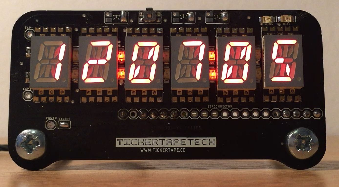
Retro Display
Scrolling multicharacter display

![]() Launched on kickstarter
Launched on kickstarter
 Join the conversation over in our Discord Server!
Invite Link
Server
Specification
- 3.3v - 6v DC
- I ² C Interface
- Arduino AVR / ESP32 / RaspberryPi
- Dimensions: 79mm x 41mm x 1.6mm
- 4 buttons, or 4 touch points.
The display board works with 3.3v or 5v micro controllers no problem, as the LED driver is constant current. In my testing I have found that I can power the display with 5v and the micro controller at 3.3v (with its on-board regulator) no problem without level shifting.
The display is multiplexed, so only a handful of LEDs are ever on at the same time, so I have also found that I can use the voltage rail of the micro controller without an issue too. So the display is very flexible.
You can set the overall display brightness in code with 16 brightness levels.
The board layout has positions for 4 buttons, but these can also be used as touch inputs if your micro controller supports this (The ESP platform has native support, and there is an Arduino library for touch inputs too)
Hardware
The PCB file is in Eagle format, and can be found on github:
Whats on the board
The back of the board is simply an LED driver IC, and a bypass capacitor.
There are component pads for additional hardware the user can choose to add themselves.
The front of the board is a bit more complicated. We have the 14-segment display modules, 12 LEDs, and two pullup resistors for the I2C data bus.
If you are building a kit - then it is best to use a reflow oven for the topside parts and then hand solder with an iron the rear side IC and cap. Or use a hot air gun rework technique. It is possible to solder the 14-segment displays with a soldering iron - its just a bit tricky. I have done it with a lot of patience and flux. There are 6 'blind'/inner pads - that are tricky. But they do have a via in the SMT pad. My technique was wet those pads on the board with a minimal of solder (use some solder wick if its too bumpy), add flux, and place the display element onto the pads. Then press down with a finger, and use the tip of a soldering iron with a small amount of solder to reflow the pad from the top, and if all goes well the solder and heat will pass through the via and flow the solder below making the connection. Repeat for all the hidden pads, and then use a more standard approach to solder the outer pads. This is a hard technique to get a pretty result. A hot air gun and solder paste might be a better option.
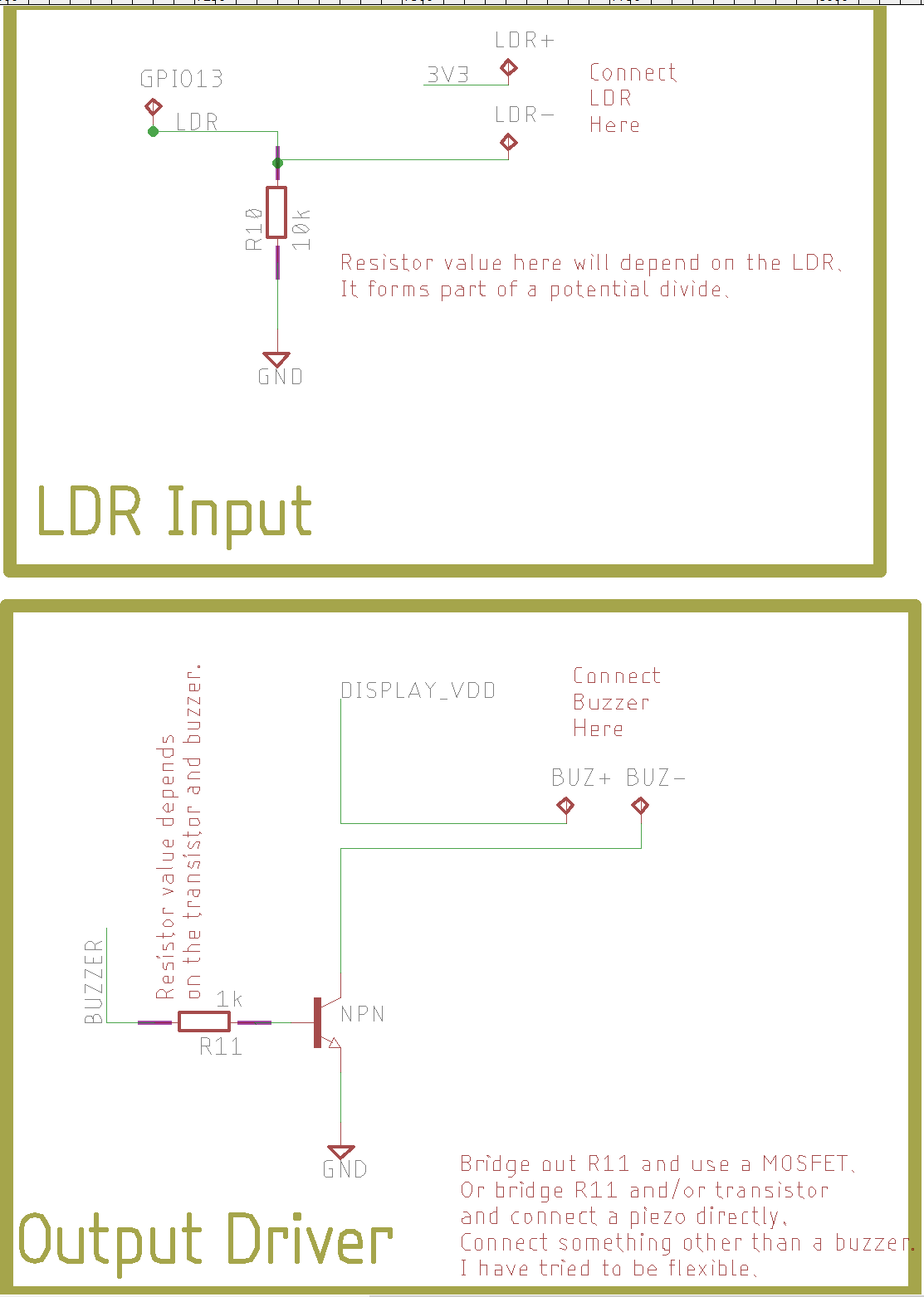
Schematic
Diode orientation
If you are building one of these boards make sure you have the diodes the correct way around, use a multimeter to check! The triangle mark shown here was not on the silkscreen layer when I sent the first boards for manufacture.
If you backed the kickstarter and choose one of the kit rewards, then please check and double check the LED anode (+) and cathode (-) orientation with a multimeter. In the kit you will have 11 red LEDs on a bandolier, and one blue LED.
I have created a little testing Arduino Sketch - that will check every LED on the board in a sequence - so you can check everything was soldered correctly. https://github.com/darrendignam/TT_Display_TestEachLEDElement/blob/master/TT_Display_TestEachLEDElement.ino
If you are hand soldering the board, you can solder the IC and bypass capacitor (the bottom side of the board), connect your Arduino or ESP to the display and run the check as you are doing the soldering on the top side to make sure all is well as you are working.
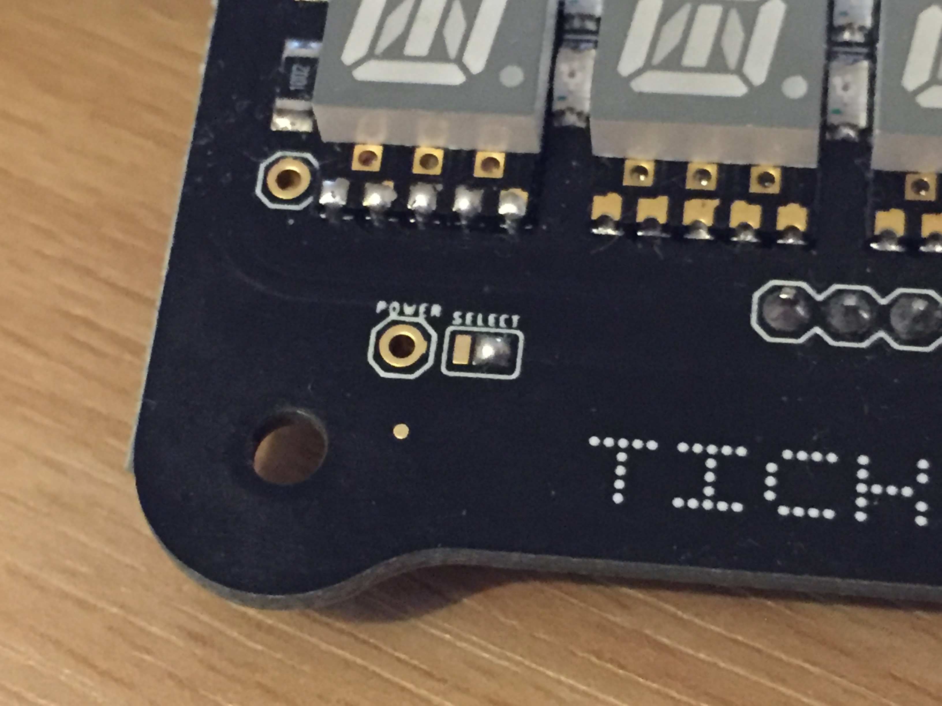
Power Jumper
If your tickertape does not seem to be powering up, check this little jumper on the front. It lets you choose which pin supplies power to the dissplay IC. The ESP connector 3.3v pin (that matches the same pin on the LOLIN32 CPU board). Or the pin called power. If you want to have your own batter power, or 5v from a usb cable, then use this pin.
This is the device set to use the ESP32 3v3 power pin.
Inputs and Outputs
I have added some additional pads for resistors and transistors squeezed into the space on the back of the board, if you want to use them to add features, then please check the schematic for how these are hooked up to the connectors. The choices of components one could use is too large for me to explain of choose here, but I would suggest making a mockup on breadboard first, before soldering anything. If you find some good components and ideas for these - then please share them with with us over on the discord server.
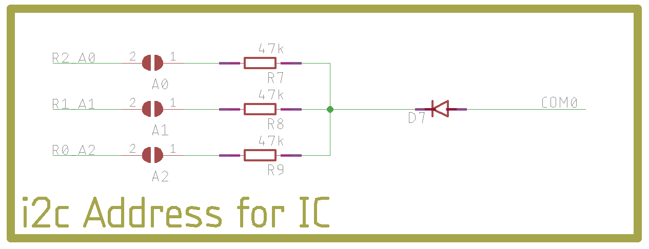
Address Jumpers
The final additional feature is the ability to change the default address of the display IC on the I2C bus. For people with many sensors or other hardware this might be useful. Please check the Holtek datasheet for additional info. You will also need to make changes to the firmwware to use the new address, all the libraries have the default address - but this can be over ridden by passing the new address to the constructor.
Software
The below instructions are for the ESP32, and getting you setup to install the base firmware for the display, like what was on the boards when the backers got them.
There will be more generic instructions further below soon.
Arduino & PlatformIO
My reasoning, is that using a more modern and capable IDE like Atom or VSC makes working with very large and complex projects a lot easier as you get tips and hints from the IDE while writing your code (less compiler errors) and you get autocomplete at times too, I use VSC for all my coding, and it iss a very capable IDE. There is a bit of a learning curve to get a new project off the ground, but hopefully as I have already done that - things should be easier. Plus - the last resort to getting the code to complie currently is to download the 2Gb Ubuntu disk image and run a VM, where PlatformIO is less work than that and has so many more benefits!
The main issue is libraries, versions and compiling. The PlatformIO firmware have all these packed into the project. I also find the ArduinoIDE very slow when uploading to the ESP boards, even if I dont actually make any changes to the code. PlatformIO can be a bit slow on the first upload, but afterwards, it only compiles code that changes - so becomes much faster after that.
I really recommend wathing this video by Andreas Spiess to get a good understanding of the framework
Install Guide:
- Install The latest ArduinoIDE: https://www.arduino.cc/en/Main/Software
- (Optional) Install Visual Studio Code: https://code.visualstudio.com/
- Install PlatformIO: https://platformio.org/install/ide?install=vscode
- Download the firmware from github:
Arduino setup & ESP32 Instructions
-
To program the software of the Retro Display you will need to follow some steps. The first is to get the Arduino IDE setup on your computer. Please follow the instructions from the Arduino website:
Choose to download and install the actual IDE, not the cloud editor.
-
Now we need to get the Arduino IDE to recognise the ESP boards. Sparkfun have a really good guide on getting the arduino IDE setup and ready to go, so I will link it here and you can follow their instructions.
The entire post here is good information, but for our needs, just add the ESP32 family of boards to the Boards Manager.
You should be able to connect the device to the computer and in the arduino IDE, choose the COM port, and select the ESP Board. In the 'Tools' dropdown you should be able to choose the 'WEMOS LOLIN32' as your board, and then try some of the examples too.
If you can get some of the basics like blink working with the onboard LED (pin 5 by the way) then please continue.
-
The next step is to get the various libraries needed by the display. Besides the main ESP32 CPU, there is an LED Driver chip on the board a Holtek chip. Rather than reinvent the wheel - I have used the AdaFruit github libraries for Arduino as a starting point. You could use their libraries from the Library Manager, but I have made some changes to the code in my own fork that make it better suited to the Retro Display, so I suggest manually downloading the following and putting them into your library folders. There are a couple of other dependencies that I also tweaked for the display.
Goto each of the following github projects, and download a zip by hittin the big green 'Clone or Download' button in the top right of the page, and choose 'Download Zip' (if you are happy to use git tools to do this, please do so, but I am keeping things simple here).
Once you have the zip files for each project - unzip them into the library folder. This folder is in your sketchbook folder where arduino stores your sketches, its found in the current users home folder area, on windows this is:
C:\users\YOUR_USERNAME\Documents\Arduino\libraries\
But will be a similar folder on Mac and Linux too.-
https://github.com/adafruit/Adafruit-GFX-Library
The AdaFruit GFX library, used by a lot of their other libraries, if you have their products already, you might have this already.
-
https://github.com/darrendignam/Adafruit_LED_Backpack
My Tweaked Version of the Backpack library that talks to the Holtek Chip
-
https://github.com/darrendignam/LED_Display_Wrapper
My wrapper library for the above backpack library that makes scrolling text and handling the display a bit easier.
-
https://github.com/darrendignam/WIFIMANAGER-ESP32
This is an essential library for doing cool webserver stuff with the ESP boards, I have forked and tweaked it to integrate with the display board so the display shows connection related stuff when we need it. you could happily use the original by zhouhan0126
-
There is one final library that is really hard to find now. It was originally for the ESP8266 and when I built the project, it wasnt fully ported over to the ESP32. Trying to recreate the firmware from scratch, I had problems with this one. The official version looks to be here: https://github.com/espressif/arduino-esp32/tree/master/libraries/WebServer and I will look at updating the code base to use the official version of the webserver, but for now, lets do what we know works.
So the final library we need is the WebServer one. Download and unzip into the library folder.
In addition to these core libraries - you might want some additional support libraries. I use a JSON one and a youtube one for the two firmwares below. (The JSON library has had a big overhaul in version 6 and its not backwards compatible with verion 5 code, so in the library manager choose the highest version 5.x.x which is 5.13.2 right now). In the Arduino IDE use the 'Sketch' dropdown menu, then 'Include Library' and the top option 'Manage Libraries...' to open the library manager. From here search for and add:
You might want to restart the Arduino IDE now to let the new libraries update into the IDE
-
https://github.com/adafruit/Adafruit-GFX-Library
-
I had trouble at this stage. As the code would compile and upload the below firmware, but the ESP board was getting stuck in a reboot loop. I found rebooting my laptop - seemed to resolve the issue.
The serial monitor is useful to have on at times like these as you can see some debug info from the ESP before usercode exceutes - and you can see if the ESP itself is rebooting and why. In my case it looked to be something to do with the FS.h which is a library that allows persistent data for things like the Wifi Password to be saved between reboots. I am going to look into this more. But the above steps on this page allowed me to sucessfully install the base firmware onto my testing retro display.
If everything has gone well, you should be able to program one of the firmwares onto the ESP. The basic firmware is a clock and weather information. The youtube firmware will show subscriber counts for a channel. With both firmwares you should look into the code and find where the API keys are, and update them with your own. I have used my own key for the weather key, but I expect this key to become disabled as more tickertape users start using the devices and it reaches past it's free limits and they will expect us to pay them. However if you goto the website and get a free account, and use your own API Key you should be OK as the firmware only updates the weather ever hour or so ( you can edit this of course).
This firmware is a bit rushed, but I plan to make it better, and put it in github so we can all collectivly improve it.
Unzip the firmware into you sketchbook folder in your home directory, which on windows is something like C:\users\YOUR_USERNAME\Documents\Arduino\ but with your user name, or the Arduino folder in your Mac / Linux home directory.
Once you have the firmware folders in the correct folder, they should appear as projects in your 'File > Sketchbook' dropdown menu in the Arduino IDE.
Remember to change the API settings if needed. Select the correct COM port, and board type - then hit 'Upload' and the firmware should work. Please head over to the discord server if you have any issues.
VirtualBox image firmware programming
Below is a link to a minimal ubuntu desktop machine that has ArduinoIDE, and the required libraries needed to program the firmware onto the ESP boards. It has the stock firmware and the YouTube firmware included in the sketch folder too for you to play around with.
The image was created with 'Oracle Virtualbox' - but the HDD file is VMWare format, so should be possible to import to that software too.
The username is 'tickertape'
The password is 'tickertapeubuntu'- VirtualBox Tickertape Image (2Gb hosted on google drive)
If you use this image you may find that the ESP board will not reset into 'programming' mode - this is a driver issue (if you know of a better driver for the USB-Serial chip on ESP - please email me! And i will update this image!). In that case, you need to manually do that - by pulling the 0 pin to ground, there is a ground pin next to the 0 pin, so a coin or key will jumper this across and it will program the ESP.
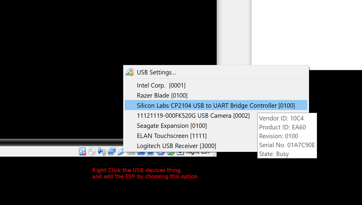
By default the Virtual Machine will not be able to communicate to the ESP board, so you need to right click the little USB icon, and pass that USB device through to the VM.
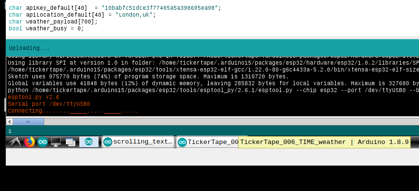
When trying to upload the code, you might see this in the ArduinoIDE output window: "....._____....._____....._____". And the device will be rebooting too. This means the device is not going into program mode. Some ESP boards have a 'boot' button to help you to get the board into the programming mode. The LOLIN board does not, but you can forcce it into that mode with this next step.
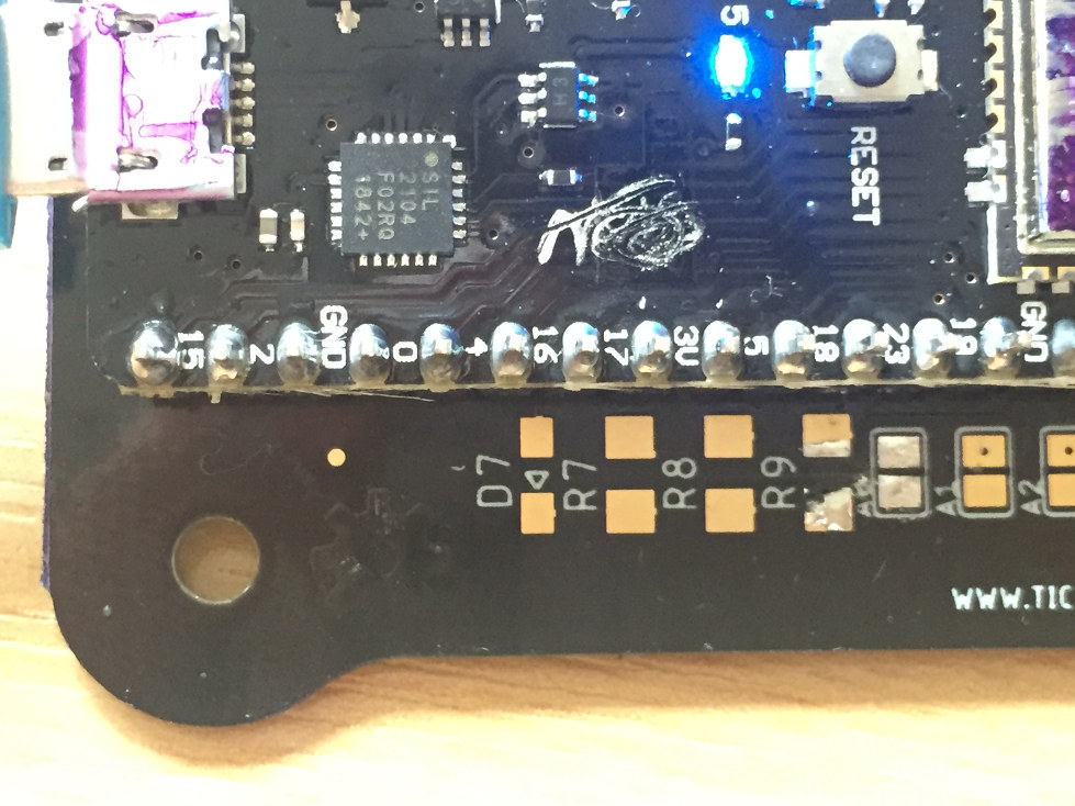
Here is a closeup of my testing board - built from the same kit I am sending out to backers. You can see the location of the 'GND' and '0' pin you need to short together.
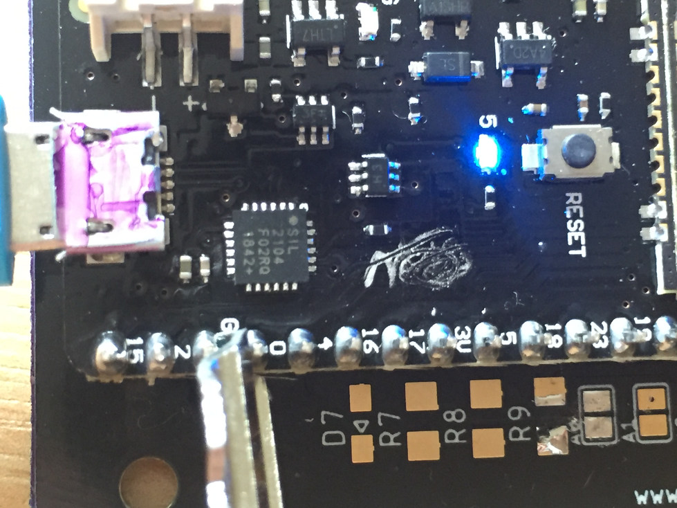
Here I am using a key to short the two pins. Hold it there until the ArduinoIDE shows it is connected. Now you can take the key (or coin) away and the code will upload.
It is useful to power cycle the display after uplaoding the new firmware just to make sure the display IC resets and any new code starts from a cold start as it were.
Development
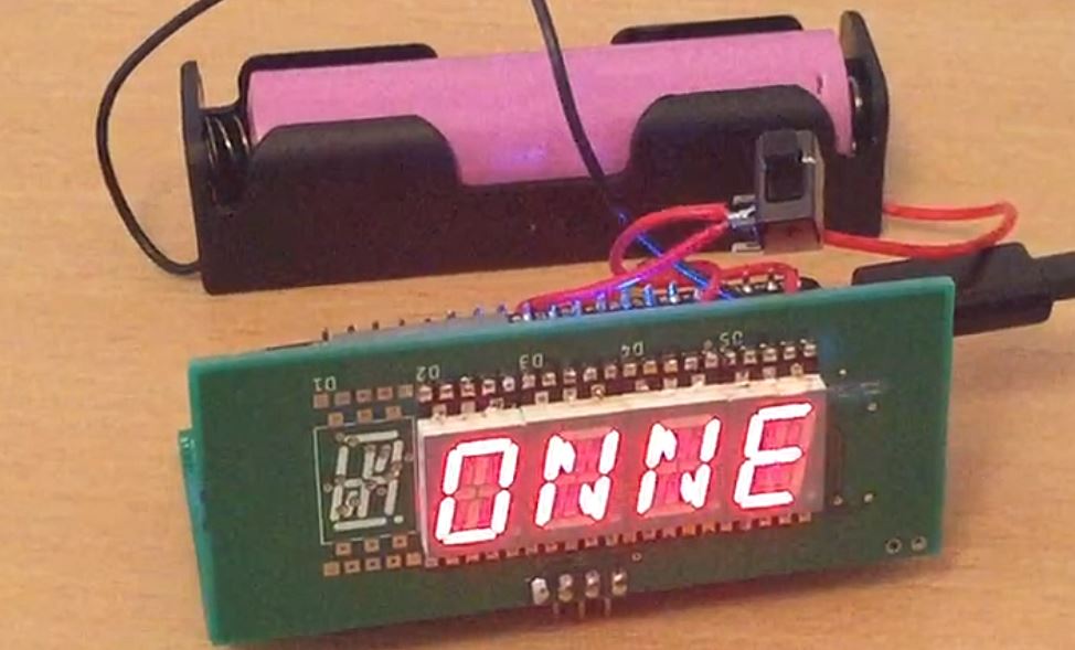
Prototype 2
This is the latest prototype which is approaching the final design. Right now looking for feedback from potential users, and producing testing versions of the display.
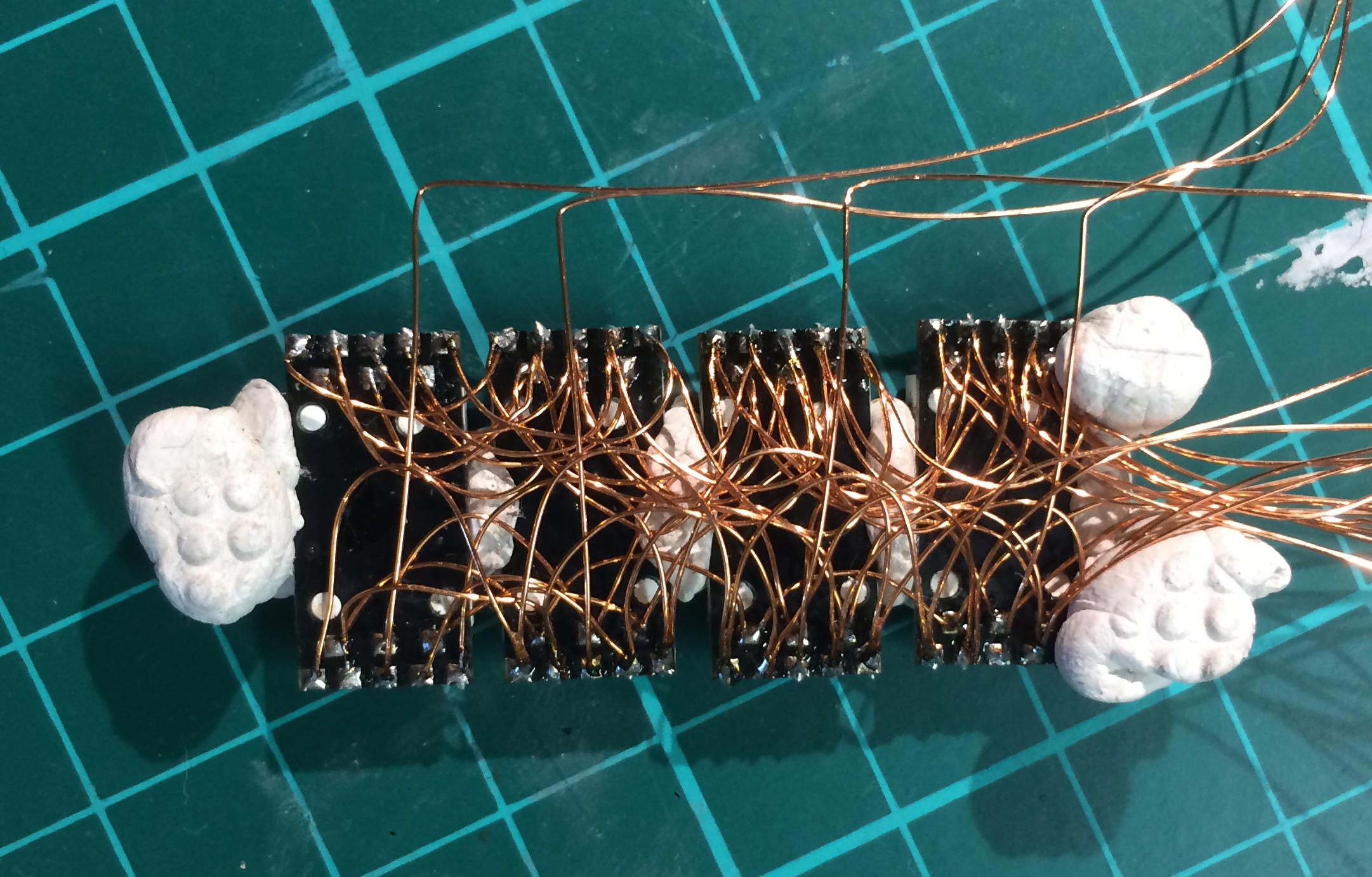
Prototype 1
After building a working breadboard display, it was time to make a schematic and board to ensure all the connections are correct.
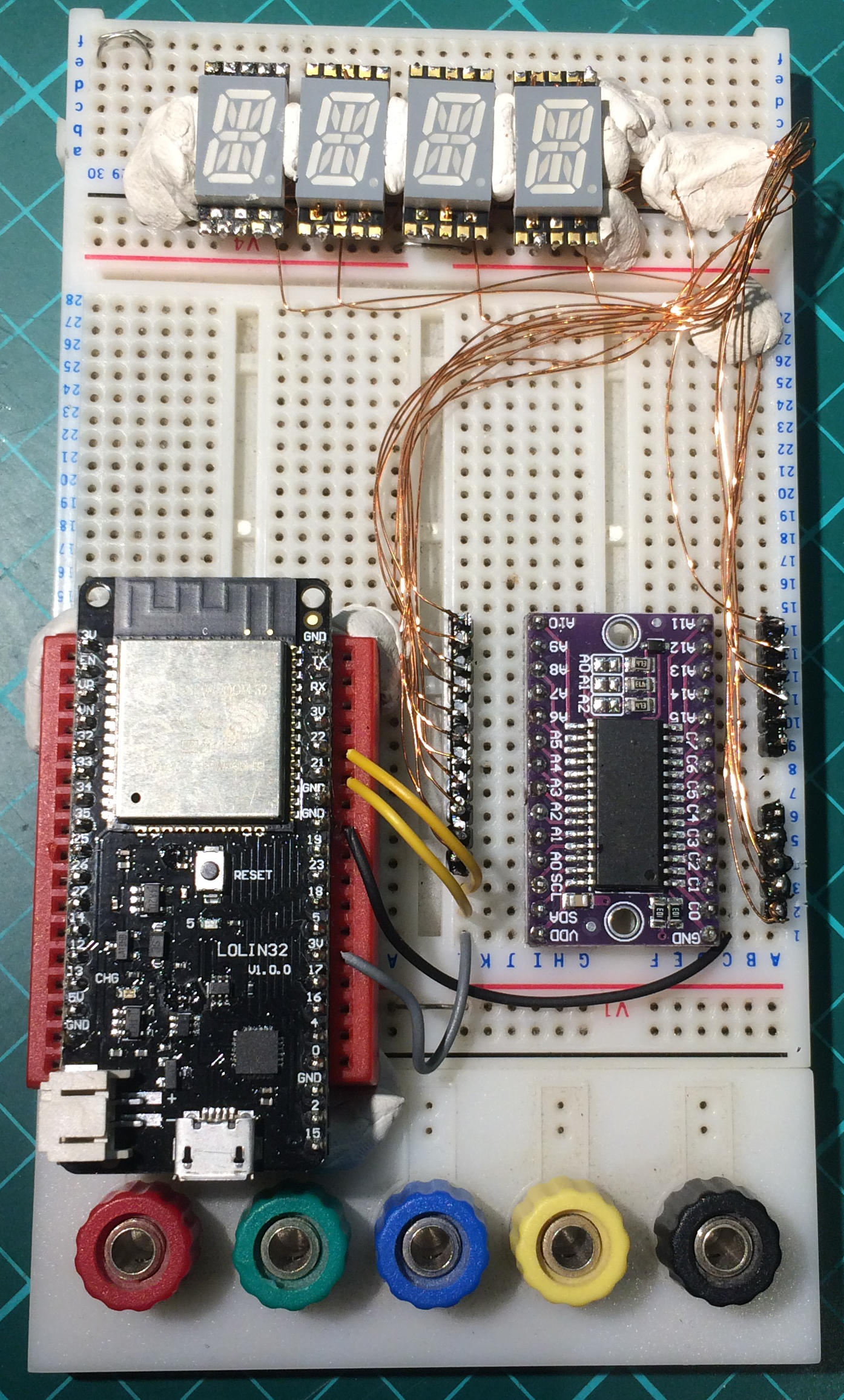
Breadboard Testing
After playing around with single display element it's time to build a bigger version. This was a tricky wiring task, but allowed the testing of the ESP32 and the Holtek LED Driver.
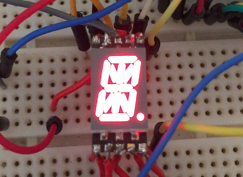
Tickertape Idea Formation
After working on other people's ideas and startups - many of which never got past the idea phase I had a bunch of my own ideas and projects I wanted to test out. This initial display is the easiest so it's also the first to test the water.
Setup
ESP32
ESP32
8-Bit Microcontrollers
Single Board Computers
Technology
- Expressive Tools
- Arduino
- Adafruit
- ???
© 2020 tickertape.cc